I always am doubting about how to irrigate my frutal trees. I can not find out how often or for how long, so I finally decide to make my own professional soil moisture multi-depth sensor to take measurements. This device will have two sensors, one will be placed at 20cm deep and the other at 40 cm deep. Registering this data via WiFi I will know how water behave in my soil, for how long I should irrigate to get water at 30 cm, when to stop to avoid water excess, and when to irrigate again.
What I will use
- 2x ComWinTop soil moisture sensors (FDR Capacitive Dielectric Sensors)
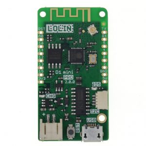
- 1x LOLIN Wemos D1 mini pro (the brain)
- 1x 5v 230mA solar panel
- 1x Battery NCR18650B (and its holder)
- 1x RS3485 module (to communicate with the sensors)
- 1x Step-up booster (to power the sensors)
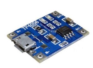
- 1xTP4056 charger module
- External WiFi antena
The sensors
The sensors are industrial grade. They are available with different options, to measure Ph, moisture, temperature, and NPK. And with different information output modes: voltage, current or RS485.
I have chosen two sensors with only moisture and temperature measurements (3 probes) and RS485 output.
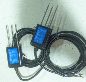
I have measure the consumption of two of this sensors working together and it is about 50mA at 5v, but oscillating between 30-50mA with sometimes peaks to 70mA. It means from 0,25W to 0,5W.
The ESP8266 board
I am using a LOLIN Wemos D1 mini Pro v2.0.0 for this project:
- It has an built in battery charger (where I will connect a solar panel)
- It has an interface for Lithium battery (where I will connect a 18650 battery)
- It makes simple reading the battery value (through A0 pin, previous connecting SJ1)
- It has a connector for an external WiFi antena
- It has three Solder Jumpers:
- SJ1 (BAT-A0): Connects battery voltage to pin A0 (analog input)
- SJ2 (LDO_EN): Allow disabling the 3.3v regulator
- SJ3 (SLEEP): Connects RST pin to GPIO16 to allow waking up from sleep mode.
The solar panel and the battery
As this is going to be in a field where there is no easy way to power any device the project must run on batteries. My first thought was to run it on 2xAA batteries, but then I decide to add a solar panel and a NCR18650B battery to make thinks easier. The Wemos D1 mini pro has an integrated charger, but you could use a different board (without builtin solar charger) combined with a TP4054 battery charger module. I bought a solar panel 5v 230mA (100x82mm). My project will be sleeping or working based on the battery level, but in my area there is lot of sunny hours, so this will not be problem.
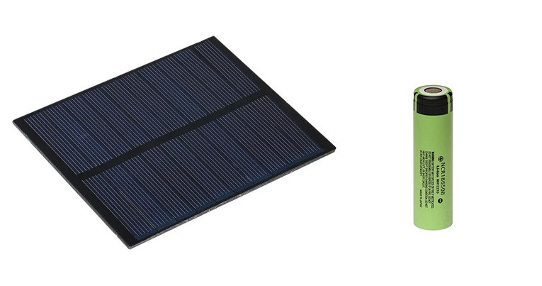
The solar panel will be connected directly to the USB charge port of Wemos D1 mini pro v2 because it includes a battery charger. Another option will be using an external charger, a TP4056 module. I am testing these two different options and my first findings are that if the battery is fully depleted D1 mini pro charger is not able to charge it, but TP4056 external module do it perfectly. Perhaps D1 mini pro charger is designed to get more power in its charger port, perhaps it requieres enough power to power up the D1, the RS3485, the step up, the sensors, and charge the battery. While TP4056, when battery is depleted, cut off al the loads and puts all solar power into charging the battery.
The RS3485 module
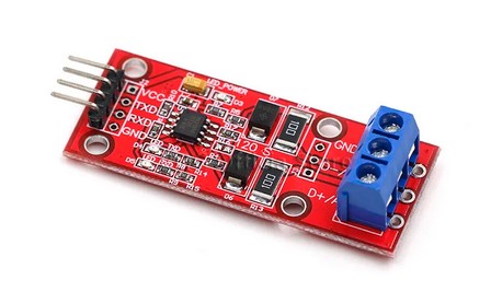
The CWT soil sensors speak RS485 protocol, so I need a RS485 module. The most common ones use 5v, but the one with the MAX3485 chip works on 3.3v, so I will use that.
The step-up
CWT soil sensors must be powered from 4.5v to 30v so I need a power source of at least 4.5v. My power source is my NCR18650B battery which runs on 4.2v to 2.9v so I need some kind of booster to get 5v to power the sensors. Here we can choose between two options, a Wemos Battery Shield, which incorporates a 5v step up booster (among another unneeded things) or using a specific step booster (MT3608). I will try both of them.
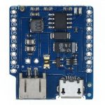
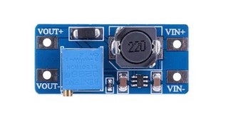
I have compared these two step up boosters and they are very similar in consumption, but the D1 Battery Shield stops working when input voltage is about 3.10v, however MT3608 go further. Stop working means it stop giving 5v to the sensors.
Note: I have tried powering up the sensors with 3.3v and they works, but I am not sure about how precise they are. Perhaps with some more tests I could avoid using a step up. And I have found some more info about this behaviour here.
Finally my tests confirms that sensors are not precise enough at 3.3v. I must use the step up booster to power them with 5v.
Let’s build!
1. Set up sensors
Both sensors have ID = 1 so they can not live together into the same RS485 bus. So I have to rename one of them to ID = 2. This was really easy using the software of ComWinTop (configtool.exe). Connect one of the sensor to your PC and rename its ID. Now I have a sensor with ID = 1 and other with ID = 2, and I can query any of them independently.
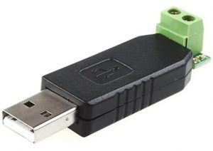
Note: You will need an USB to RS485 adaptor to connect the sensor to your PC, like this one, to change the ID of one sensor.
This sensors support more configuration options, like moisture offset, temperaure offset or modbus speed, but I do not need those options at the moment.
2. Set up the board
On the Wemos D1 mini pro I have to spin (desolder, spin, and solder) the 0K resistance to enable the external antena connector.
I also have to solder SJ1 (BAT-A0) to allow reading battery voltage through analogic input (A0).
And I also have to solder SJ3 (SLEEP) to allow set a timer to wake up the ESP8622 from sleep.
3. Software
I am using Arduino IDE to make a simple code which reads the moisture and temperature from sensor with ID 1 (burried at 20cm), reads the moisture and temperature from sensor with ID 2 (burried at 40cm), reads the battry voltage (from A0) and publish all this data to a MQTT broker (which runs into a Raspberry Pi among a Home Assistnat and a Grafana).
4. The case
I will use some recycled material… I will see.
Testing power consumption
The solar panel gives me lot of room, so I only have to get the project running by itself for about 24h. Daylight will charge the battery. However get 24h running on battery is not too easy. I have tested without connecting the solar panel with a full battery, deep sleeping the ESP8266 for 5 minutes, waking it up, reading values and publishing them and sleeping again, and it last for about 6-8 hours. So I have taken some measurements to understand what pieces are wasting more power. Long story short, the sensors are wasting 40-70mA all the time, even when deep sleeping. I have to solve this, using some kind of transistor or FET to disconnect the sensors power when sleeping and connect when needed. Even better, disconnect the step up, which will disconnect the sensors too. These are some measurements:
| Element | Running | Deep sleeping |
|---|---|---|
| Full project | 150-180mA | 40-70mA |
| Disconnecting sensors (but keeping the step up powered up) |
7mA | |
| Disconnecting step up (which also disconnects the sensors) |
0.1mA |
And what about other elements? RS3485 communication module is powered up by 3.3v, and it consumes about 7mA. I could switch it off when deep sleeping the same way, with a transistor or a FET, but there is a easier way, powering through a GPIO. I have connected RS3485 vcc pin to GPIO5 (pin D1) and I put this GPIO high when needed and low when deep sleeping.
Let’s take some measurements.
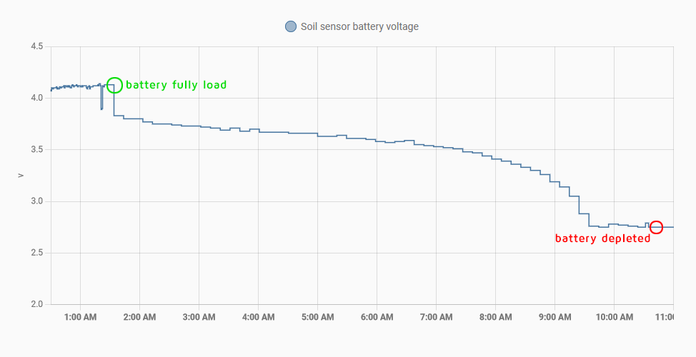
This graph shows the battery voltage, i.e. the discharge speed, when the soil sensors are connected and receiving 5v for all the time, when D1 mini pro is awake and when it is deep sleeping (awake/sleep every 10 minutes). As you can see the battery of the 18650 only last for 9 hours! It won’t survive one night waiting for the sunrise.
However let’s check how long will last the battery when there is no sensors connected, not even when D1 mini pro is awake: After testing for seven days… Oh my God! It looks battery never runs out if I disconnect the sensors!
Disconnecting loads when in deep sleeping
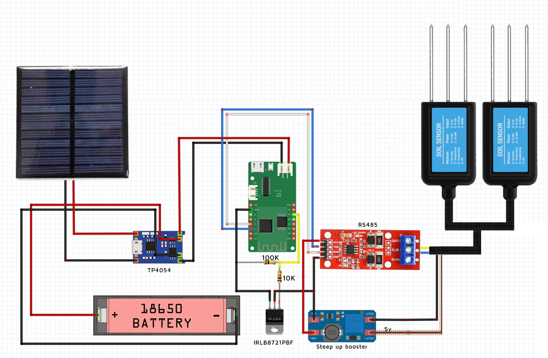
I need to disconnect the step up booster (which powers the sensors with 5v) when the project goes to deep sleep to avoid battery wasting. Furthermore, when battery is fully depleted is quite difficult charging it with a small solar panel while sensors are consuming a big part of the energy generated by the solar panel. How to switch off the sensors when I want? This is done with a FET or transistor which is controlled by a GPIO pin. But… what kind of FET or transistor do I need? It must be controlled by a 3.3v signal (the voltage of the GPIO) and it should control a 4.2-2.8v signal, the battery voltage which powers the step up. I will use a IRLB8721PBF N-Channel MOSFET and connect it in a low side switch configuration, using a pair of resistors too, one to avoid floating ground (100K) and another to protect the D1 pin (10K). So I will put it into the ground cable of step up booster and I will control its gate from pin D2 (GPIO 4 ). This way I can swith on and off my step up booster and my sensors to reduce consumption.
The schematics A draw
Show me the code!
I am using Arduino IDE to make the code. In brief the code does:
- Enable step up booster and RS485 module (activating gate of IRLB8721P MOSFET low side switch)
- Try to connect to WiFi (if not, abort and deep sleep)
- Read 20cm depth sensor humidity and temperature
- Read 40cm depth sensor humidity and temperature
- Read battery voltage
- Connect to MQTT broker and publish the values
- Deep sleep for 10 minutes
You can view the full code in my github
Possible improvements
- Avoid using a solar panel and run on 2xAA batteries. It will be posible with some changes. Disabling some components of the board like the UART CH340, or even better, not using a development board and build the project with a bare ESP8266. Furthermore reduce power consumption using a different wireless technology, as LoRa or ESP-NOW. This could allow making this project without the need of a solar panel. But… you will have to replace your 2xAA batteries at least once a year, so… why? A solar panel is great!
- Check CRC response
- Power the step up (positive wire) directly from battery, and not from D1 Wemos D1 mini Pro.
- Add a third sensor into a third depth level
Installation
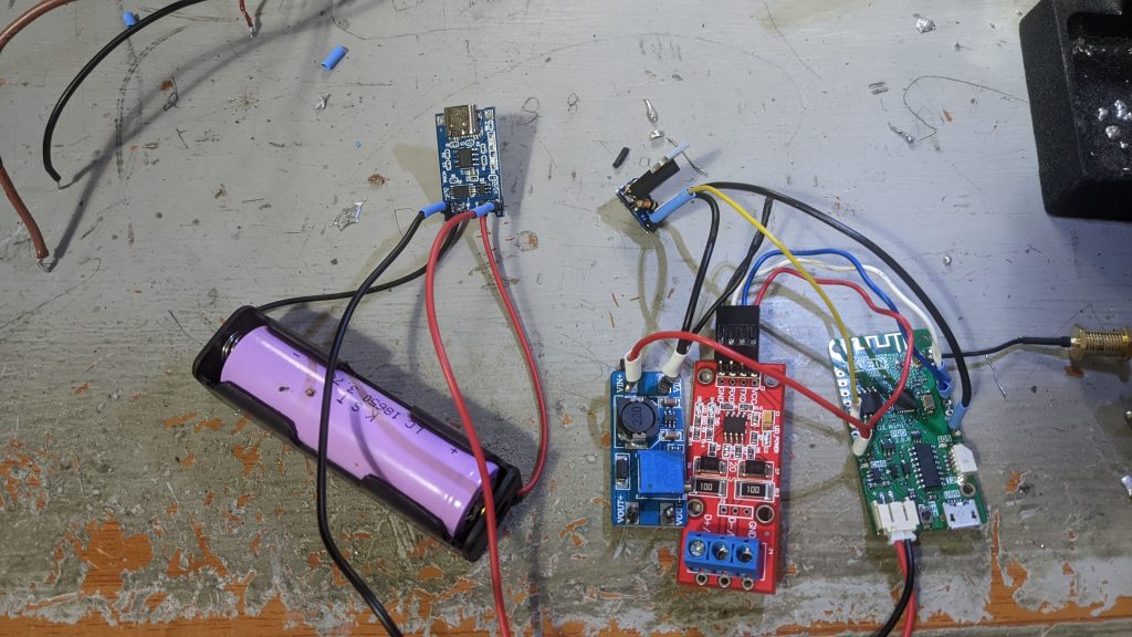
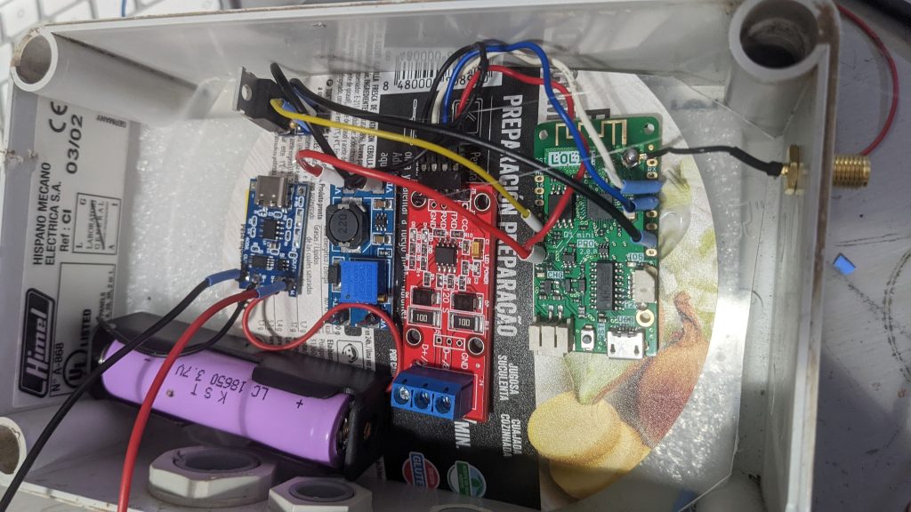
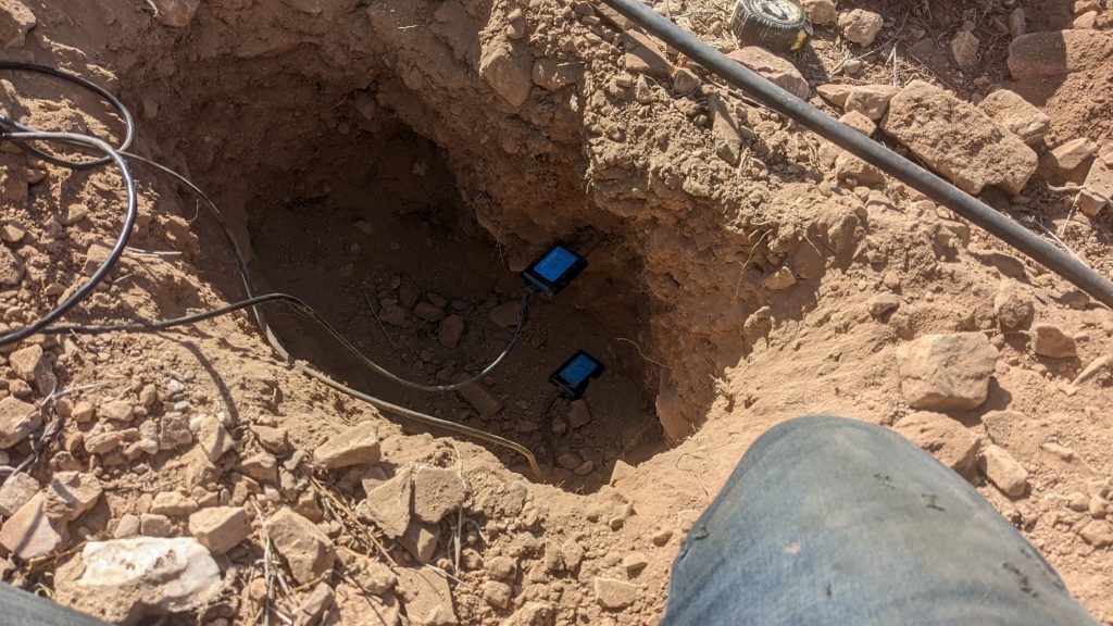
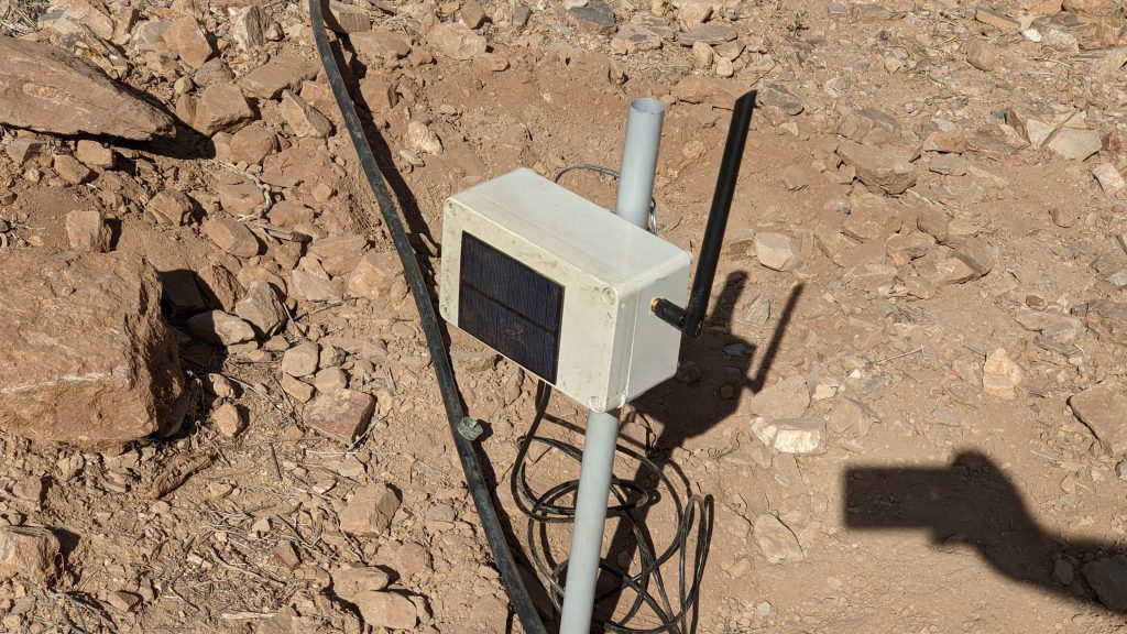
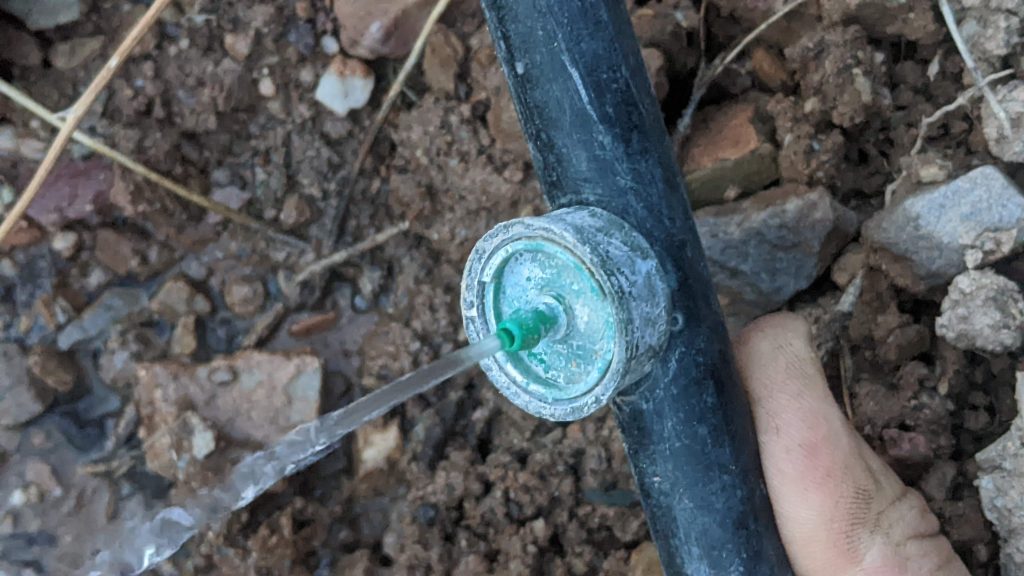
Once I have the circuit assembled and working it is time to make a hole and burry the sensors, one at 20cm and the other at 40 cm
Using the data
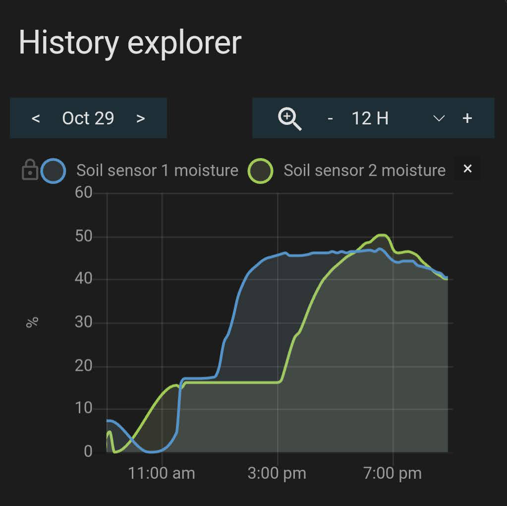
As you can see, after start irrigation at 11:30 am, the first graph sensor at 20 cm (blue line) gets saturated about two hours, but sensor at 40 cm (green line) takes longer, almost seven hours.

Now is time to get more relevant findings. For that we first need to understant some easy concepts about soil and irrigation:
- Field Capacity is when the soil is not able to hold more water. If you continue irrigating water gets drained (wasted)
- Permanent Wilting Point is when your plants can not get any water of the soil, even though there is water left yet.
- Available water is the water between Field Capacity and Permanent Wilting Point. Easy.
- Maximum Allowable Depletion is the portion of available water we should allow deplete, because bellow this threshold the plants face water stress. There is water that can be adquired by plants yet, but they need a big effort to get it.
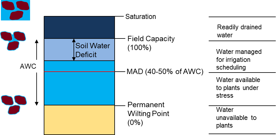
So when we irrigate we want to get Field Capacity moisture because plants can get water with no effort.
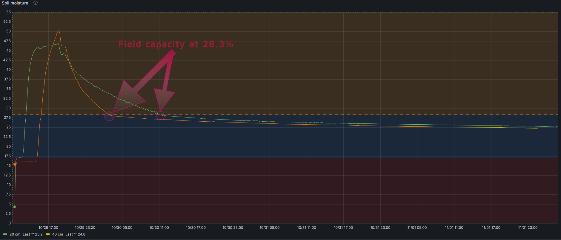
How could I know what is the Field Capacity of my soil using my sensors?
If you look at long run graphic you will see than the line goes down quickly (water excess) and at some point it goes down softly. That exactly point is Field Capacity. Just when the soil finish draining the water it cannot hold.
How could I know what is the Permanent Wilting Point of my soil?
This is a difficult point to get, as it depends not only on the soil but also on the crop. But it can be estimated following this formula
PWP= -5+0.74xFC by Silva et al., 1988
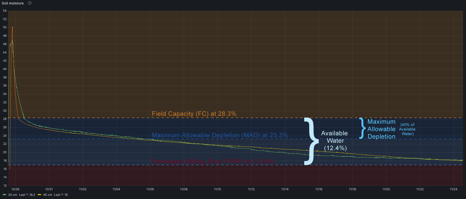
In my case, taking into account that Field Capacity is 28.3%:
PWP=15.94%
And then Available Water is 28.3-15.9=12.4%
How could I know what is the Maximum Allowable Depletion of my crop?
My crop is Pistachio Trees and FAO (Food and Agriculture Organization of the United Nations) determines that maximum allowable depletion is 0.40.
So I should irrigate when my soil lost 40% of Field Capacity water, this is when my soil moisture sensor indicates 23.3%
As a note, FAO also determines maximum rooting depth, and in Pistachio Tree is 1-1.50 meters
More info in FAO irrigation and drainage paper 56
In summary
Conclusions
- I should irrigate until soil sensors get 28.3% of moisture (Field Capacity)
- I should wait until soil sensors get 23.3% of moisture (depleteion of 40% of Available Water)
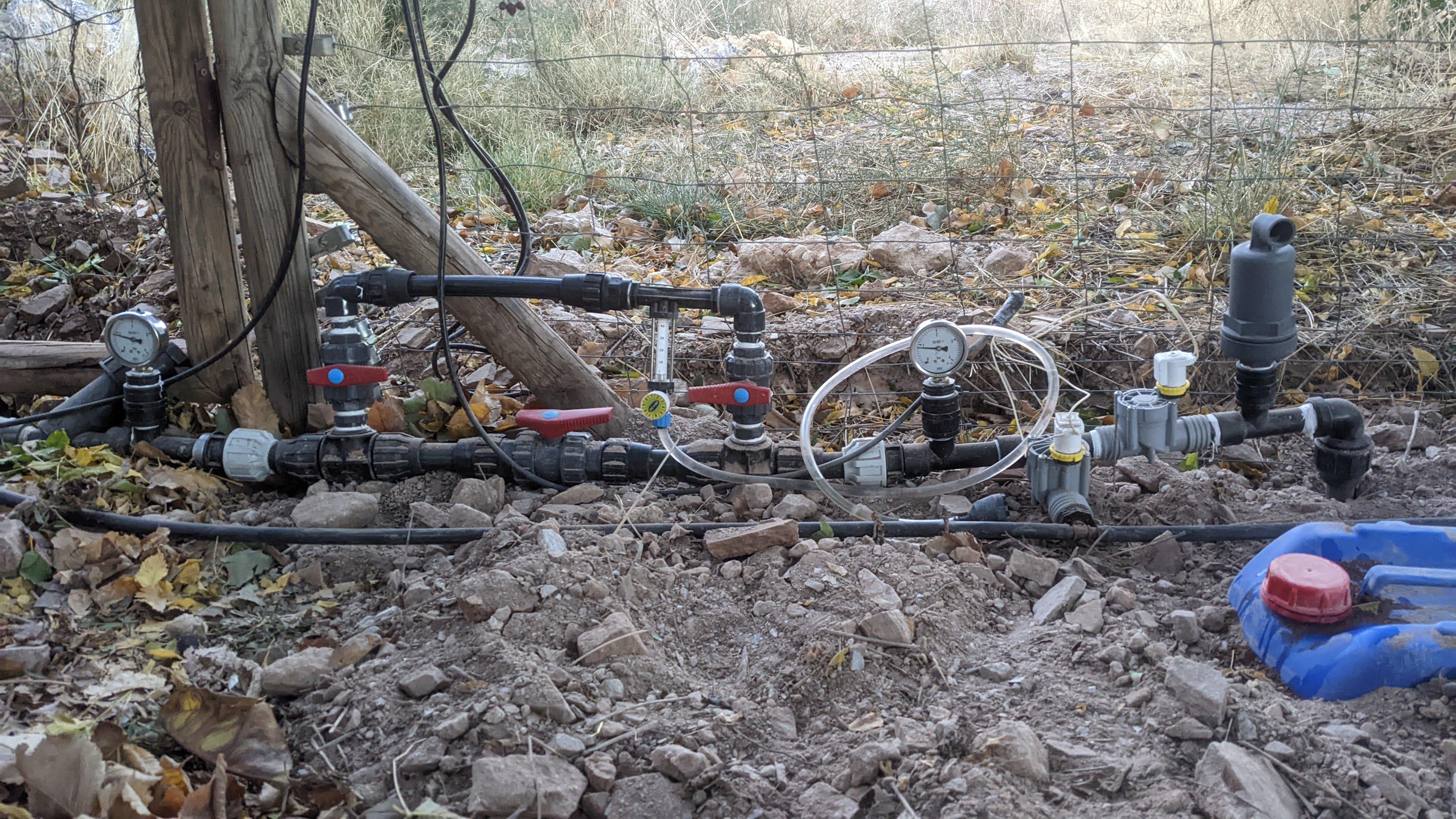
As I have a Raspberry receiving soil sensor data and controlling irrigation (with 220v solenoid valves) all this will be automatic.
Other data
Other data storer are soil temperature (at 20 and 40 cm), relation between temperature and moisture or battery voltage, as you can see in this figures.
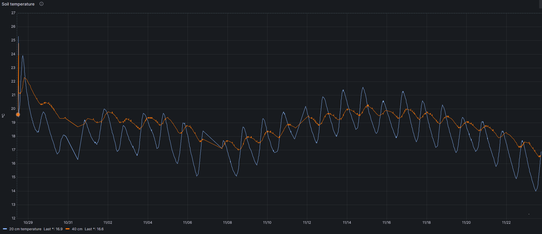
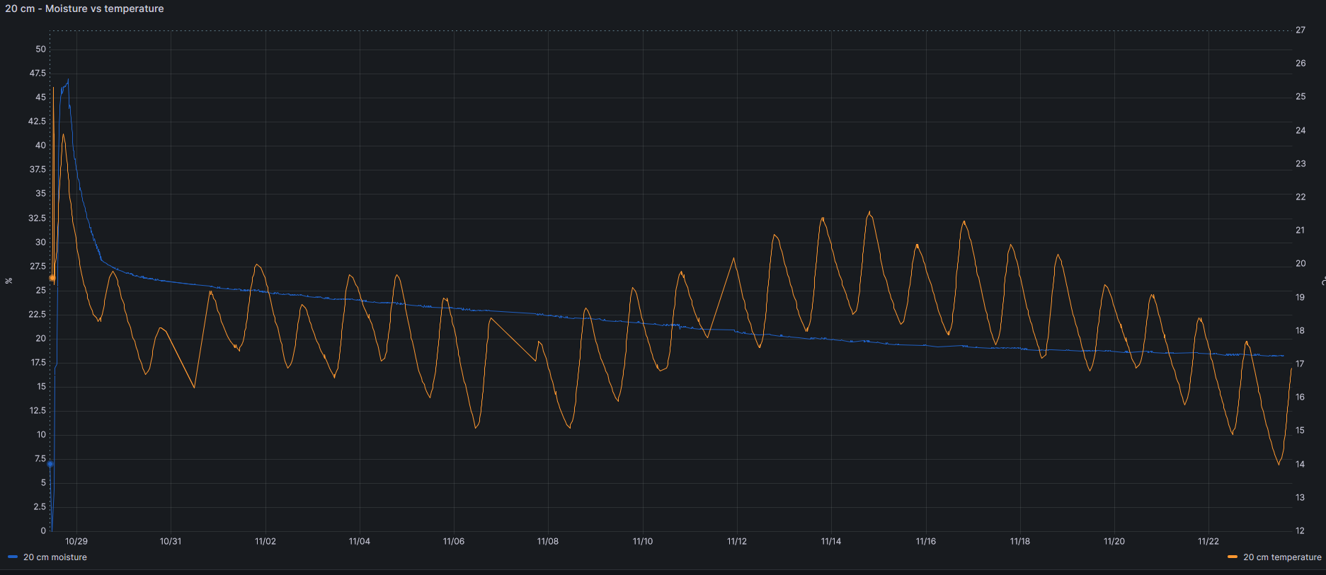
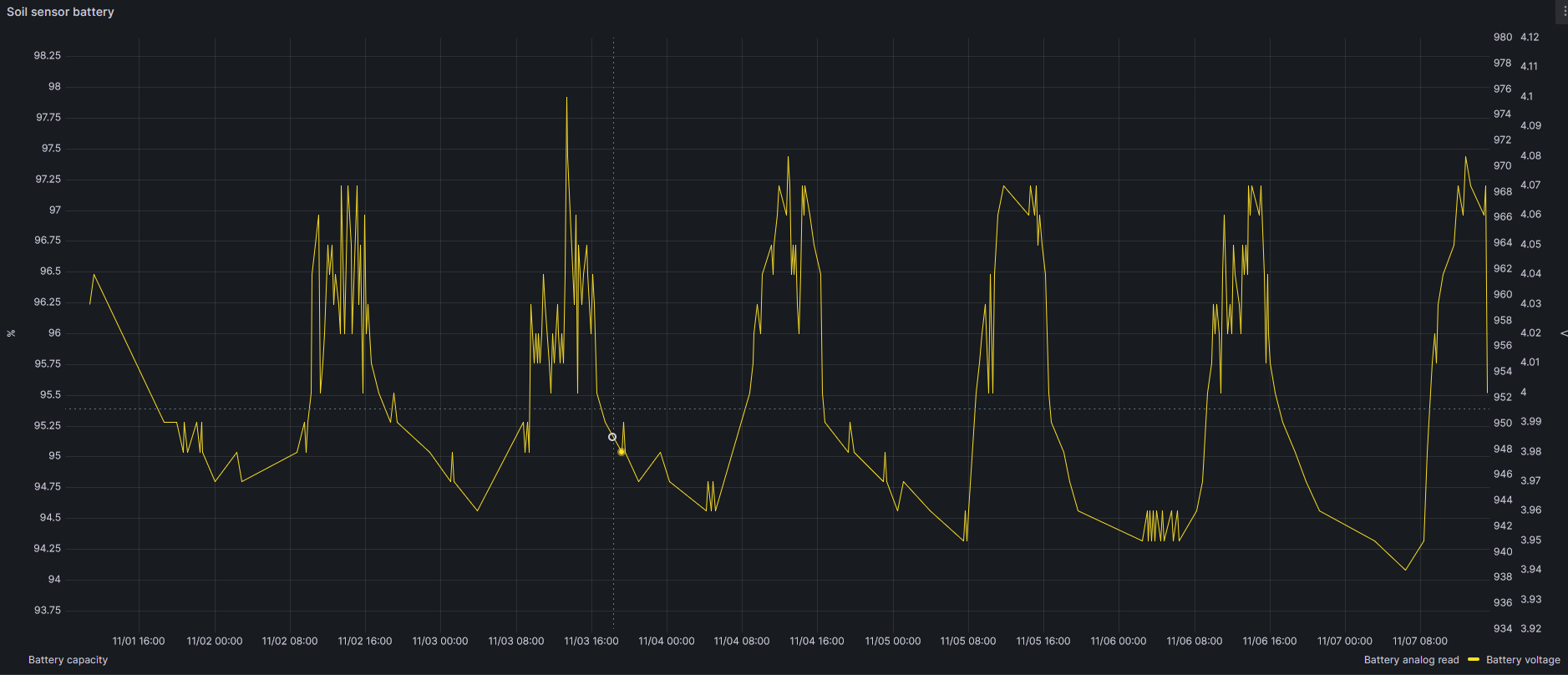
More findings will be shared in this post. Stay tuned.
Update: I have been playing with the sensors to investigate how the water moves through the soil. This graph shows short irrigation periods and moisture levels at different depths, when trying to get field capacity with short irrigation periods with a 2.2L/h emiter.
I tried to get Field Capacity at 40 cm deep with the draining water of 20 cm level, with no luck. So I finally irrigate again getting Field Capacity at 40 cm.
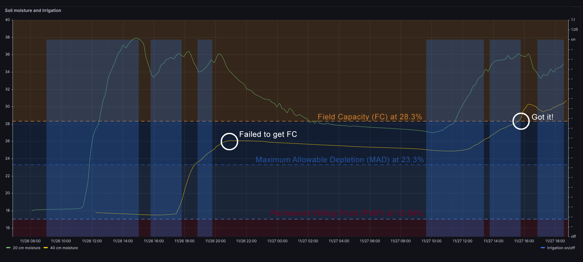
Therefore with a 2.2L/h emiter the figure shows that it takes 1h 20m to get first moisture at 20 cm deep, and it takes about 7h 30m hours to get moisture at 40 cm level. This is some I have never discoverd without moisture sensors.
| 2.2L/h | 8L/h | |
| 20 cm | 1h20m | 1h |
| 40 cm | ~7h30m | 3h25m |
Next test will be infiltration speed with superficial organic material, and after that placing the emiter 60 cm far (horizontally) from the sensors
