Professional soil moisture sensor with ESP8266

I always am doubting about how to irrigate my frutal trees. I can not find out how often or for how long, so I finally decide to make my own professional soil moisture multi-depth sensor to take measurements. This device will have two sensors, one will be placed at 20cm deep and the other at 40 cm deep. Registering this data via WiFi I will know how water behave in my soil, for how long I should irrigate to get water at 30 cm, when to stop to avoid water excess, and when to irrigate again.

What I will use

  • 2x ComWinTop soil moisture sensors
  • 1x LOLIN Wemos D1 mini pro (the brain)
  • 1x 5v 230mA solar panel
  • 1x Battery NCR18650B (and its holder)
  • 1x RS3485 module (to communicate with the sensors)
  • 1x Step-up booster (to power the sensors)
  • 1xTP4056 charger module
  • External WiFi antena

The sensors

The sensors are industrial grade. They are available with different options, to measure Ph, moisture, temperature, and NPK. And with different information output modes: voltage, current or RS485.

I have chosen two sensors with only moisture and temperature measurements (3 probes) and RS485 output.

CWT TH-S moisture and temperature soil sensors

I have measure the consumption of two of this sensors working together and it is about 50mA at 5v, but oscillating between 30-50mA with sometimes peaks to 70mA. It means from 0,25W to 0,5W.

The ESP8266 board

I am using a LOLIN Wemos D1 mini Pro v2.0.0 for this project:

  • It has an built in battery charger (where I will connect a solar panel)
  • It has an interface for Lithium battery (where I will connect a 18650 battery)
  • It makes simple reading the battery value (through A0 pin, previous connecting SJ1)
  • It has a connector for an external WiFi antena
  • It has three Solder Jumpers:
    • SJ1 (BAT-A0): Connects battery voltage to pin A0 (analog input)
    • SJ2 (LDO_EN): Allow disabling the 3.3v regulator
    • SJ3 (SLEEP): Connects RST pin to GPIO16 to allow waking up from sleep mode.
LOLIN Wemos D1 mini pro v.2.0.0

The solar panel and the battery

As this is going to be in a field where there is no easy way to power any device the project must run on batteries. My first thought was to run it on 2xAA batteries, but then I decide to add a solar panel and a NCR18650B battery to make thinks easier. The Wemos D1 mini pro has an integrated charger, but you could use a different board (without builtin solar charger) combined with a TP4054 battery charger module. I bought a solar panel 5v 230mA (100x82mm). My project will be sleeping or working based on the battery level, but in my area there is lot of sunny hours, so this will not be problem.

5V 230mA solar panel and NCR18650B battery

The solar panel will be connected directly to the USB charge port of Wemos D1 mini pro v2 because it includes a battery charger. Another option will be using an external charger, a TP4056 module. I am testing these two different options and my first findings are that  if the battery is fully depleted D1 mini pro charger is not able to charge it, but TP4056 external module do it perfectly. Perhaps D1 mini pro charger is designed to get more power in its charger port, perhaps it requieres enough power to power up the D1, the RS3485, the step up, the sensors, and charge the battery. While TP4056, when battery is depleted, cut off al the loads and puts all solar power into charging the battery.

TP4056 battery charger
TP4056 external module battery charger

The RS3485 module

RS3485 3.3v module
RS3485 3.3v module

The CWT soil sensors speak RS485 protocol, so I need a RS485 module. The most common ones use 5v, but the one with the MAX3485 chip works on 3.3v, so I will use that.

The step-up

CWT soil sensors must be powered from 4.5v to 30v so I need a power source of at least 4.5v. My power source is my NCR18650B battery which runs on 4.2v to 2.9v so I need some kind of booster to get 5v to power the sensors. Here we can choose between two options, a Wemos Battery Shield, which incorporates a 5v step up booster (among another unneeded things) or using a specific step booster (MT3608). I will try both of them.

One option: D1 Battery Shield
Another option: MT3608 step up booster

I have compared these two step up boosters and they are very similar in consumption, but the D1 Battery Shield stops working when input voltage is about 3.10v, however MT3608 go further. Stop working means it stop giving 5v to the sensors.

Note: I have tried powering up the sensors with 3.3v and they works, but I am not sure about how precise they are.  Perhaps with some more tests I could avoid using a step up. And I have found some more info about this behaviour here.

Finally my tests confirms that sensors are not precise enough at 3.3v. I must use the step up booster to power them with 5v.

Let’s build!

1. Set up sensors

Both sensors have ID = 1 so they can not live together into the same RS485 bus. So I have to rename one of them to ID = 2. This was really easy using the software of ComWinTop (configtool.exe). Connect one of the sensor to your PC and rename its ID. Now I have a sensor with ID = 1 and other with ID = 2, and I can query any of them independently.

Note: You will need an USB to RS485 adaptor to connect the sensor to your PC, like this one, to change the ID of one sensor.

RS485 to USB
RS485 to USB

This sensors support more configuration options, like moisture offset, temperaure offset or modbus speed, but I do not need those options at the moment.

2. Set up the board

On the Wemos D1 mini pro I have to spin (desolder, spin, and solder) the 0K resistance to enable the external antena connector.

I also have to solder SJ1 (BAT-A0) to allow reading battery voltage through analogic input (A0).

And I also have to solder SJ3 (SLEEP) to allow set a timer to wake up the ESP8622 from sleep.

3. Software

I am using Arduino IDE to make a simple code which reads the moisture and temperature from sensor with ID 1 (burried at 20cm), reads the moisture and temperature from sensor with ID 2 (burried at 40cm), reads the battry voltage (from A0) and publish all this data to a MQTT broker (which runs into a Raspberry Pi among a Home Assistnat and a Grafana).

4. The case

I will use some recycled material… I will see.

Testing power consumption

The solar panel gives me lot of room, so I only have to get the project running by itself for about 24h. Daylight will charge the battery. However get 24h running on battery is not too easy. I have tested without connecting the solar panel with a full battery, deep sleeping the ESP8266 for 5 minutes, waking it up, reading values and publishing them and sleeping again, and it last for about 6-8 hours. So I have taken some measurements to understand what pieces are wasting more power. Long story short, the sensors are wasting 40-70mA all the time, even when deep sleeping. I have to solve this, using some kind of transistor or FET to disconnect the sensors power when sleeping and connect when needed. Even better, disconnect the step up, which will disconnect the sensors too. These are some measurements:

Element Running Deep sleeping
Full project 150-180mA 40-70mA
Disconnecting sensors
(but keeping the step up powered up)
7mA
Disconnecting step up
(which also disconnects the sensors)
0.1mA

And what about other elements? RS3485 communication module is powered up by 3.3v, and it consumes about 7mA. I could switch it off when deep sleeping the same way, with a transistor or a FET, but there is a easier way, powering through a GPIO. I have connected RS3485 vcc pin to GPIO5 (pin D1) and I put this GPIO high when needed and low when deep sleeping.

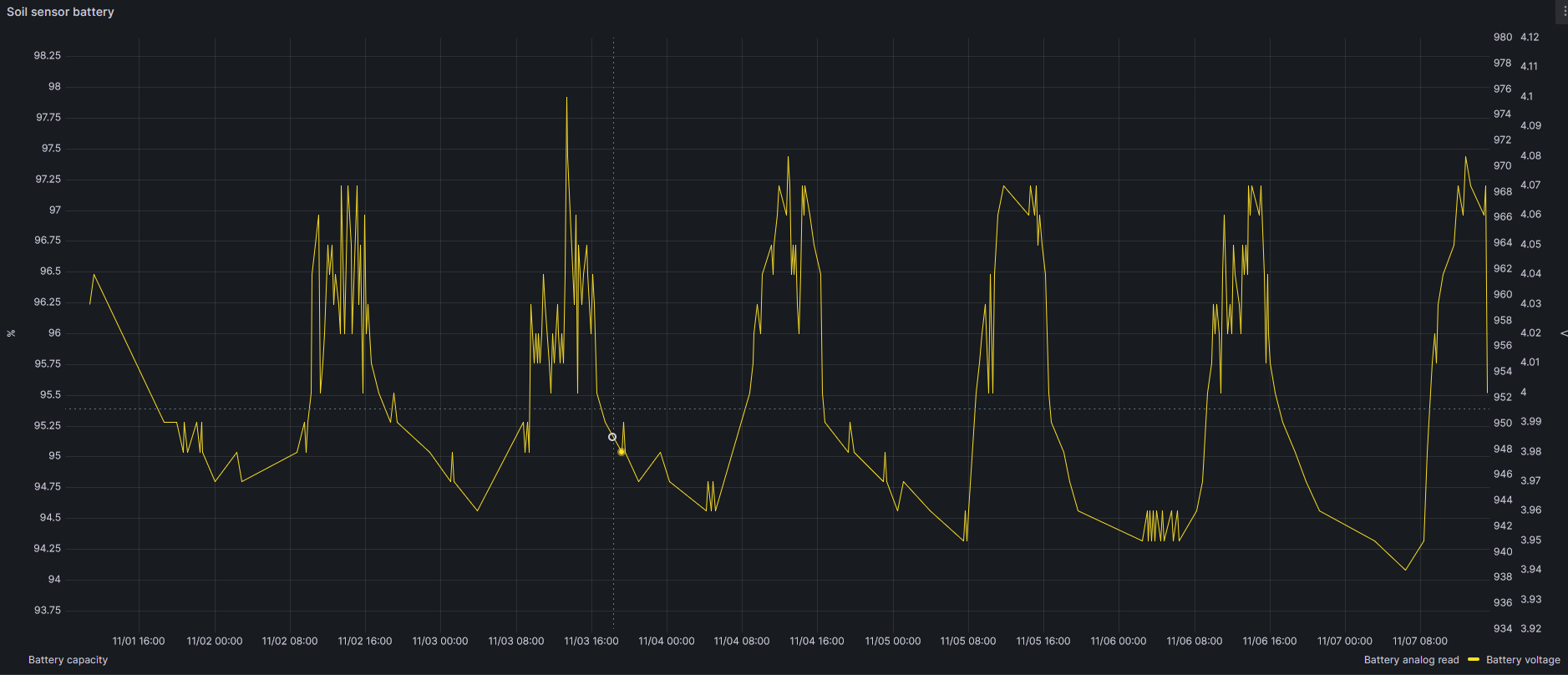
Let’s take some measurements.

Graph drawing battery voltage when soil sensors are permanently powered up
Battery voltage when soil sensors are permanently powered up

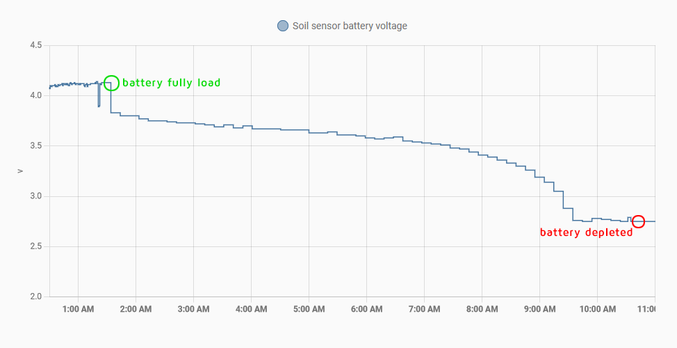
This graph shows the battery voltage, i.e. the discharge speed, when the soil sensors are connected and receiving 5v for all the time, when D1 mini pro is awake and when it is deep sleeping (awake/sleep every 10 minutes). As you can see the battery of the 18650 only last for 9 hours! It won’t survive one night waiting for the  sunrise.

However let’s check how long will last the battery when there is no sensors connected, not even when D1 mini pro is awake: After testing for seven days… Oh my God! It looks battery never runs out if I disconnect the sensors!

Disconnecting loads when in deep sleeping

I need to disconnect the step up booster (which powers the sensors with 5v) when the project goes to deep sleep to avoid battery wasting. Furthermore, when battery is fully depleted is quite difficult charging it with a small solar panel while sensors are consuming a big part of the energy generated by the solar panel. How to switch off the sensors when I want? This is done with a FET or transistor which is controlled by a GPIO pin. But… what kind of FET or transistor do I need? It must be controlled by a 3.3v signal (the voltage of the GPIO) and it should control a 4.2-2.8v signal, the battery voltage which powers the step up. I will use a IRLB8721PBF N-Channel MOSFET and connect it in a low side switch configuration, using a pair of resistors too, one to avoid floating ground (100K) and another to protect the D1 pin (10K). So I will put it into the ground cable of step up booster and I will control its gate from pin D2 (GPIO 4 ). This way I can swith on and off my step up booster and my sensors to reduce consumption.

The schematics A draw

Soil sensor schematics

Show me the code!

I am using Arduino IDE to make the code. In brief the code does:

  1. Enable step up booster and RS485 module (activating gate of IRLB8721P MOSFET low side switch)
  2. Try to connect to WiFi (if not, abort and deep sleep)
  3. Read 20cm depth sensor humidity and temperature
  4. Read 40cm depth sensor humidity and temperature
  5. Read battery voltage
  6. Connect to MQTT broker and publish the values
  7. Deep sleep for 10 minutes

You can view the full code in my github

Possible improvements

  • Avoid using a solar panel and run on 2xAA batteries. It will be posible with some changes. Disabling some components of the board like the UART CH340, or even better, not using a development board and build the project with a bare ESP8266. Furthermore reduce power consumption using a different wireless technology, as LoRa or ESP-NOW. This could allow making this project without the need of a solar panel. But… you will have to replace your 2xAA batteries at least once a year, so… why? A solar panel is great!
  • Check CRC response
  • Power the step up (positive wire) directly from battery, and not from D1 Wemos D1 mini Pro.
  • Add a third sensor into a third depth level
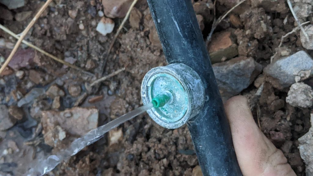
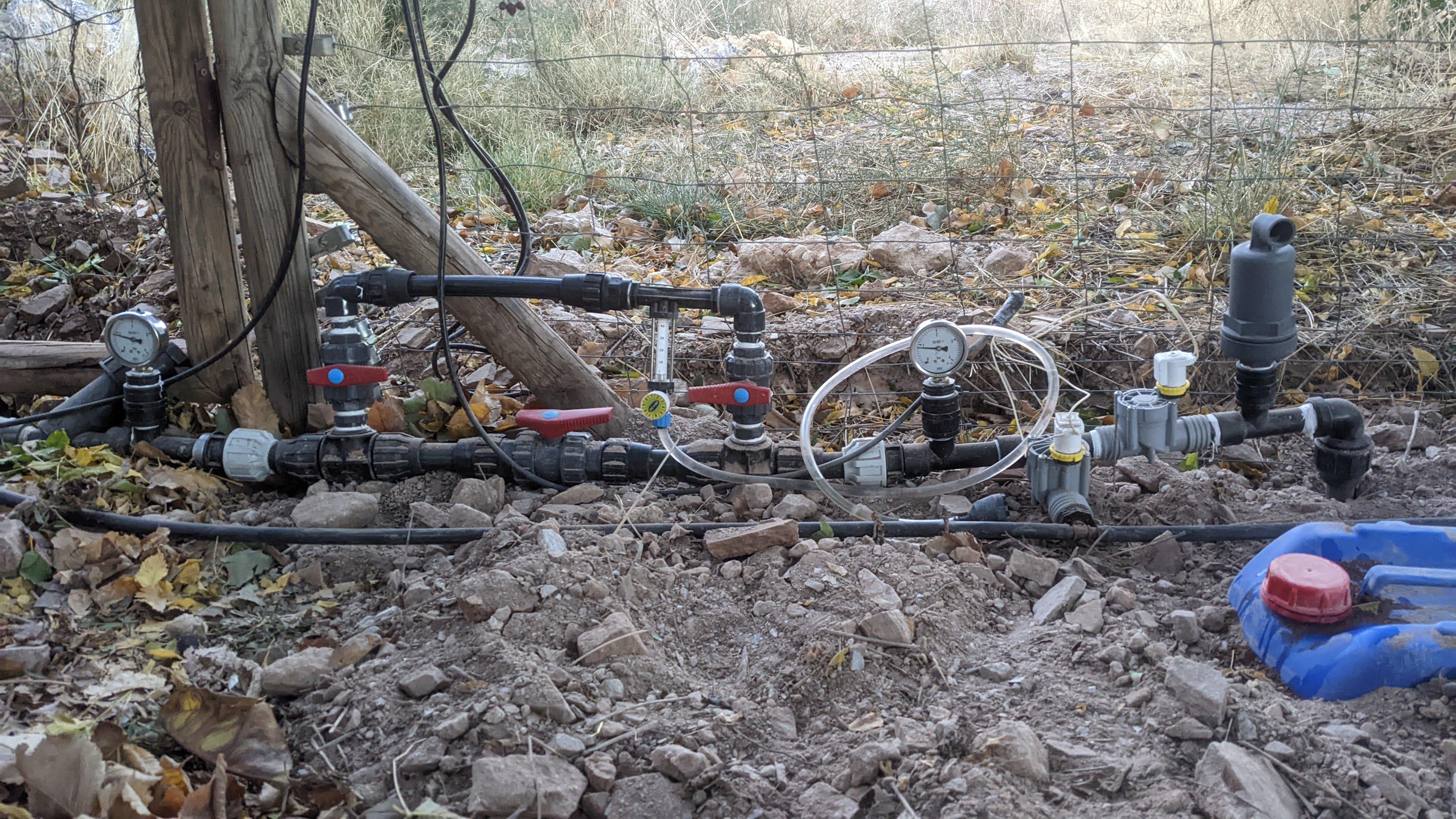
Installation

ESP8266, 18650, booster, RS485, TP4054
Real world circuit
ESP8266, 18650, booster, RS485, TP4054
Real world circuit assembled into waterproff case.

Once I have the circuit assembled and working it is time to make a hole and burry the sensors, one at 20cm and the other at 40 cm
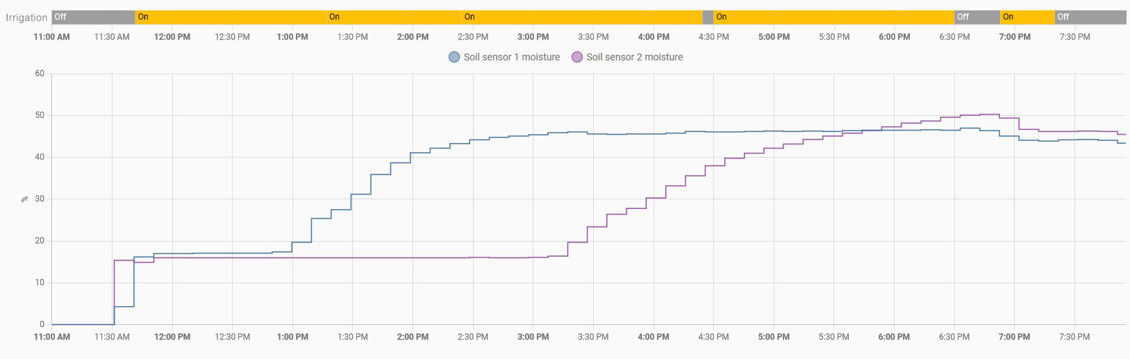
Soil sensors installed
Soil sensors working
Start irrigation
Start irrigation

Using the data

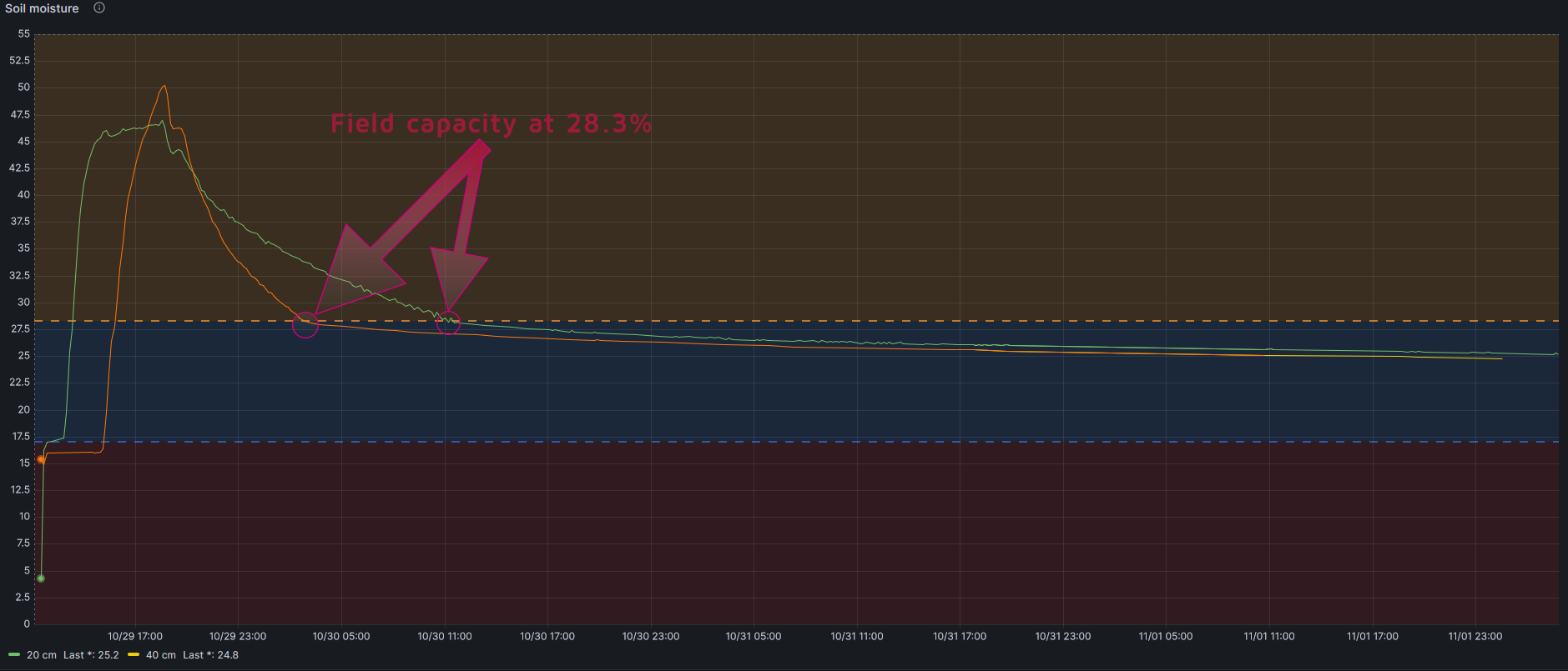
As you can see, after start irrigation at 11:30 am, the first graph sensor at 20 cm (blue line) gets saturated about two hours, but sensor at 40 cm (green line) takes longer, almost seven hours.

Initial irrigation graph (dry soil) with 8L/h emiter up to saturation at two depths
Initial irrigation (dry soil) with 8L/h emiter up to saturation at two depths
Soil sensors initial graph
Different vision of same graph

Now is time to get more relevant findings. For that we first need to understant some easy concepts about soil and irrigation:

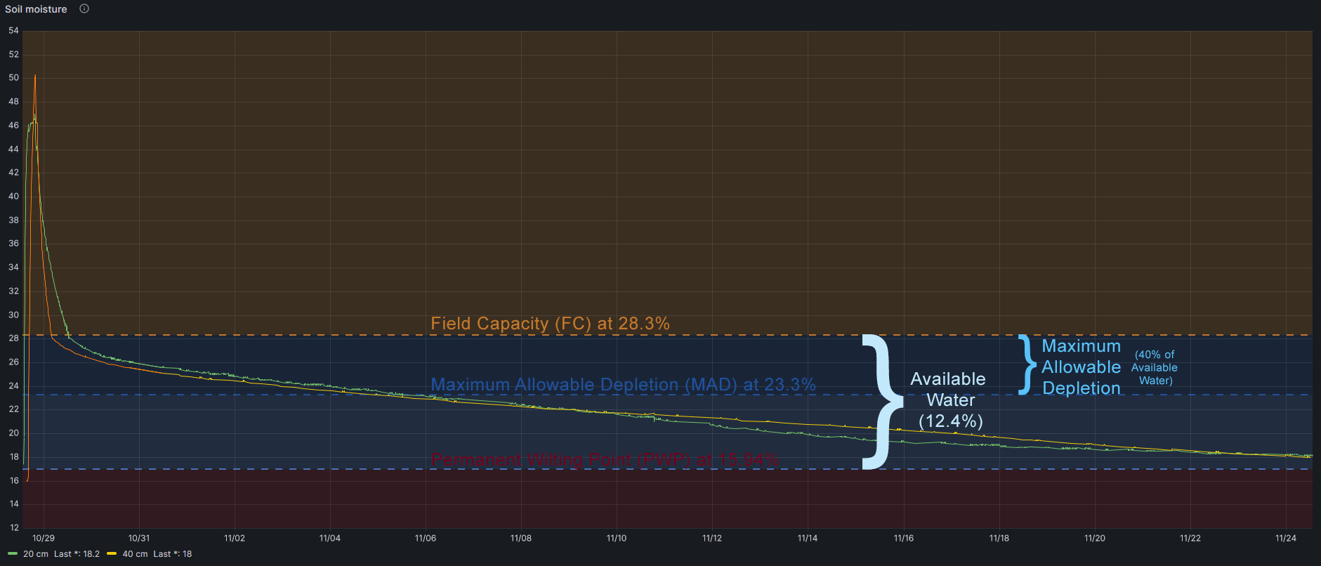
  • Field Capacity is when the soil is not able to hold more water. If you continue irrigating water gets drained (wasted)
  • Permanent Wilting Point is when your plants can not get any water of the soil, even though there is water left yet.
  • Available water is the water between Field Capacity and Permanent Wilting Point. Easy.
  • Maximum Allowable Depletion is the portion of available water we should allow deplete, because bellow this threshold the plants face water stress. There is water that can be adquired by plants yet, but they need a big effort to get it.

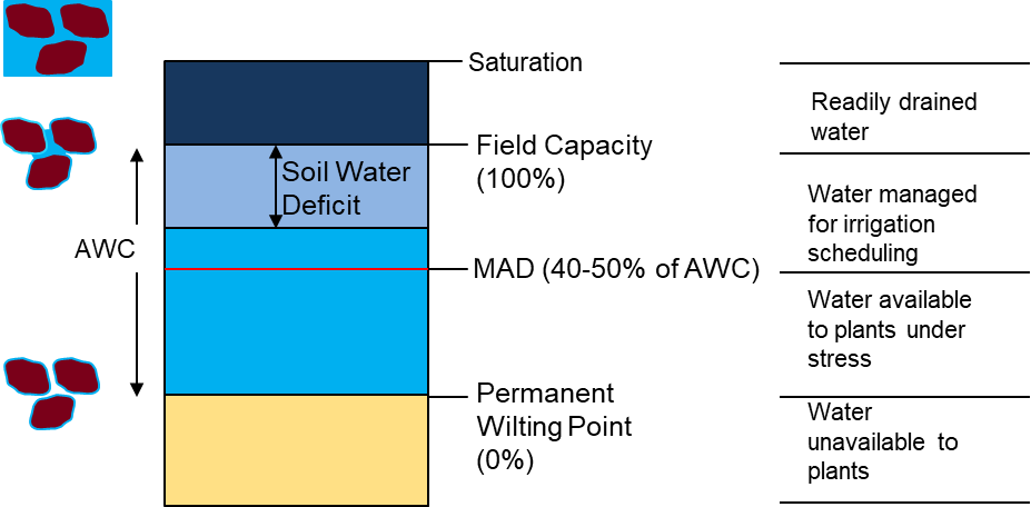
So when we irrigate we want to get Field Capacity moisture because plants can get water with no effort.

How could I know what is the Field Capacity of my soil using my sensors?
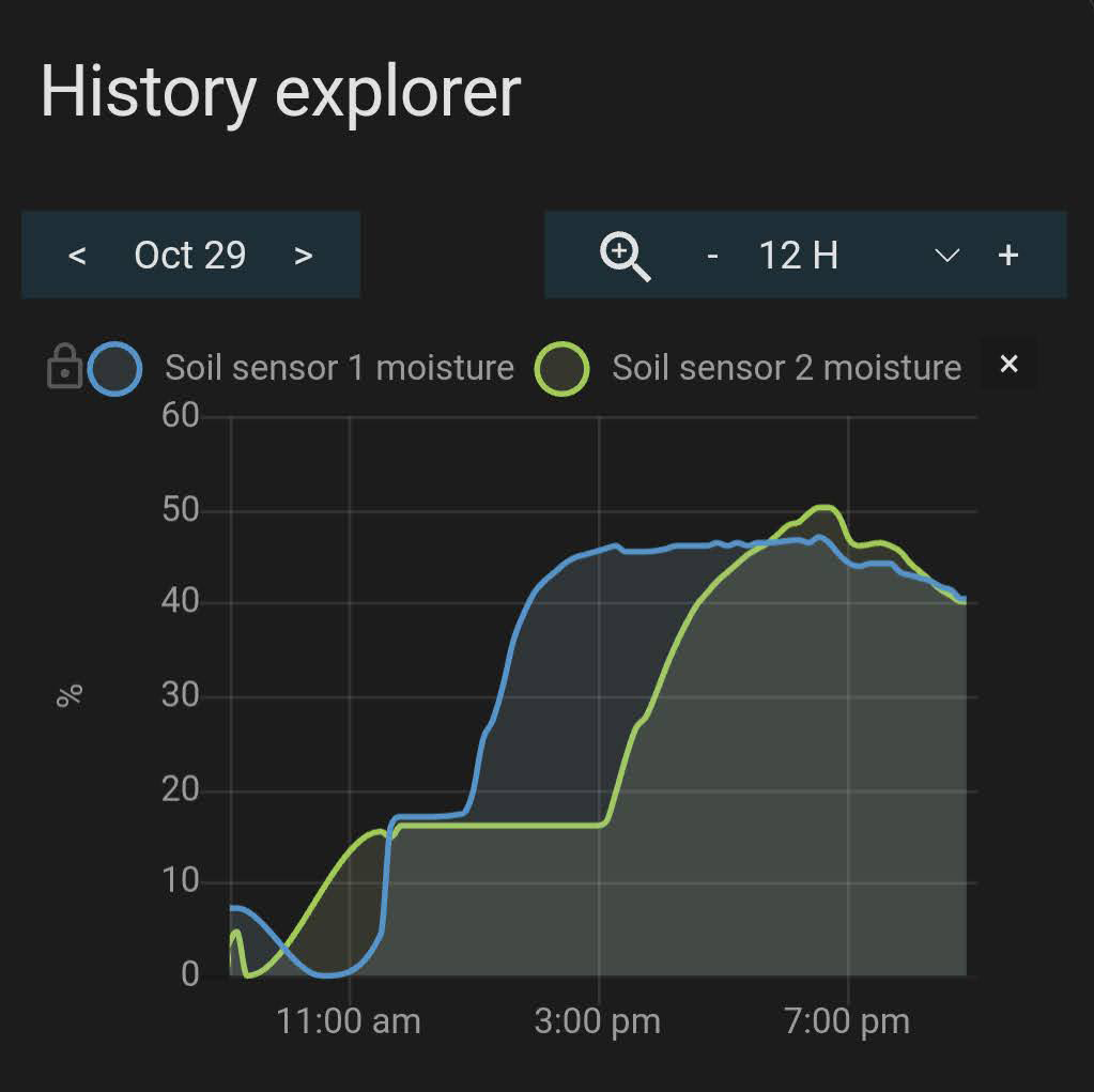
If you look at long run graphic you will see than the line goes down quickly (water excess) and at some point it goes down softly. That exactly point is Field Capacity. Just when the soil finish draining the water it cannot hold.

Field capacity with soil moisture sensors

How could I know what is the Permanent Wilting Point of my soil?

This is a difficult point to get, as it depends not only on the soil but also on the crop. But it can be estimated following this formula

PWP= -5+0.74xFC by Silva et al., 1988

In my case, taking into account that Field Capacity is 28.3%:

PWP=15.94%

And then Available Water is 28.3-15.9=12.4%

How could I know what is the Maximum Allowable Depletion of my crop?

My crop is Pistachio Trees and FAO (Food and Agriculture Organization of the United Nations) determines that maximum allowable depletion is 0.40.

So I should irrigate when my soil lost 40% of Field Capacity water, this is when my soil moisture sensor indicates 23.3%

As a note, FAO also determines maximum rooting depth, and in Pistachio Tree is 1-1.50 meters

More info in FAO irrigation and drainage paper 56

In summary

FC, MAD and PWP marked in a graph

Conclusions

  1. I should irrigate until soil sensors get 28.3% of moisture (Field Capacity)
  2. I should wait until soil sensors get 23.3% of moisture (depleteion of 40% of Available Water)

As I have a Raspberry receiving soil sensor data and controlling irrigation (with 220v solenoid valves) all this will be automatic.
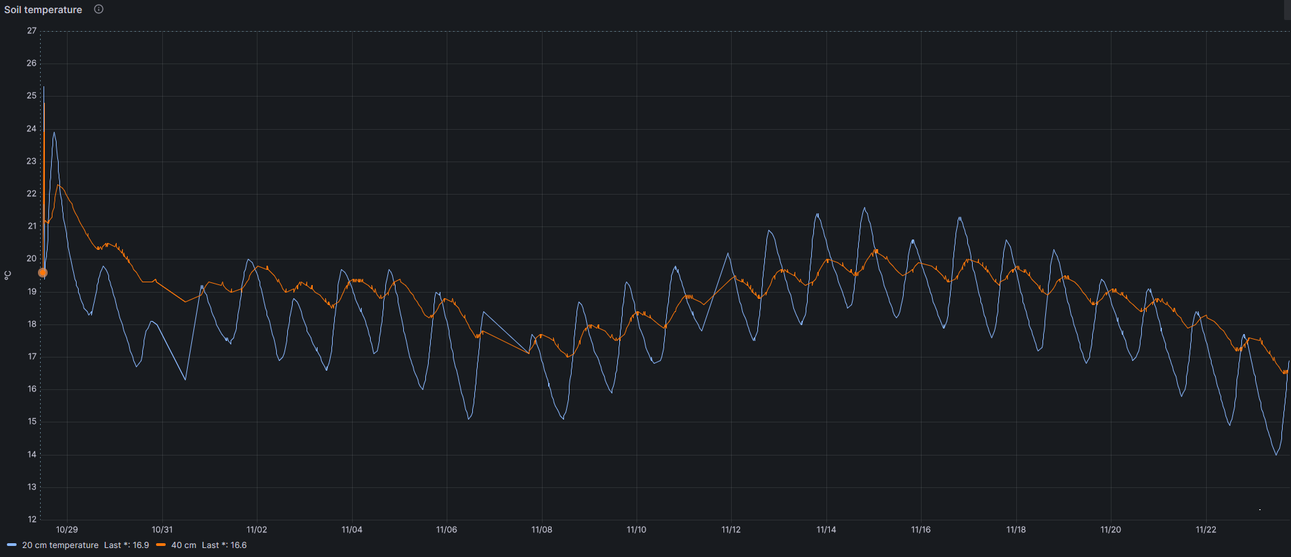
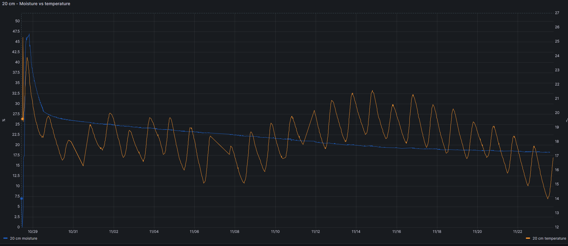
Irrigation system with 220v solenoid valves

Other data

Other data storer are soil temperature (at 20 and 40 cm), relation between temperature and moisture or battery voltage, as you can see in this figures.

Soil temperature sensor at two depths
Soil temperature vs soil moisture at 20 cm
Battery voltage through some days

More findings will be shared in this post. Stay tuned.

Update: I have been playing with the sensors to investigate how the water moves through the soil. This graph shows short irrigation periods and moisture levels at different depths, when trying to get field capacity with short irrigation periods with a 2.2L/h emiter.

I tried to get Field Capacity at 40 cm deep with the draining water of 20 cm level, with no luck. So I finally irrigate again getting Field Capacity at 40 cm.

Short irrigation period trying to get Field Capacity

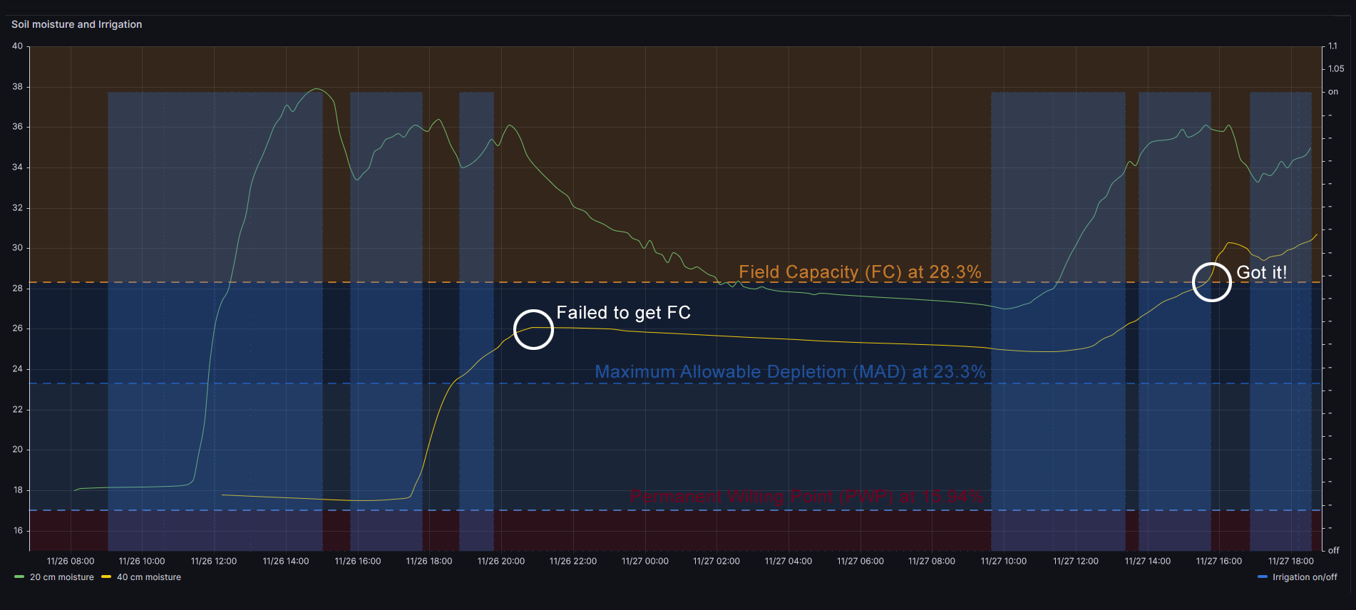
Therefore with a 2.2L/h emiter the figure shows that it takes 1h 20m to get first moisture at 20 cm deep, and  it takes about 7h 30m hours to get moisture at 40 cm level. This is some I have never discoverd without moisture sensors.

2.2L/h 8L/h
20 cm 1h20m 1h
40 cm ~7h30m 3h25m

Next test will be infiltration speed with superficial organic material, and after that placing the emiter 60 cm far (horizontally) from the sensors

How to get rid of Emotet and TrickBot

Steps:

  1. Download Rkill.
  2. Download and install last version (trial) of Malwarebytes in each PC and run an analisys once with internet connection to get latest virus definitions
  3. Disconnect all PCs from the network to avoid one infected PC reinfect one cleaned PC
  4. Run Rkill in each PC to kill any infected process
  5. Run a Malwarebytes full analisys to remove all infected files
  6. Patch every PC with this patch to avoid new infections. This will patch some exploits used by Trickbot, but there is newer versions which use other exploits.
  7. At this point Emotet and Trickbot should not be in your system, but it is so smart that it could keep hidden and reborn in a few days or weeks. So…
  8. Review process list searching for any strange process name. (I should add some powershell script here)
  9. Review schedule task to review any suspicious task
  10. Re-run Rkill + Malwarebytes every day in some random machines for a few weeks.
  11. Change all passwords. Trickbot collects any password it is able to capture. Domain passwords, email passwords, browser rememberd passwords (specially bank accounts)…

Some consequences:

  • Now I have blocked .doc, .docx, .xls, xlst email attachements by default.
  • I am thinking about changing jobs

Compartir el puerto 443: Apache y Exchange

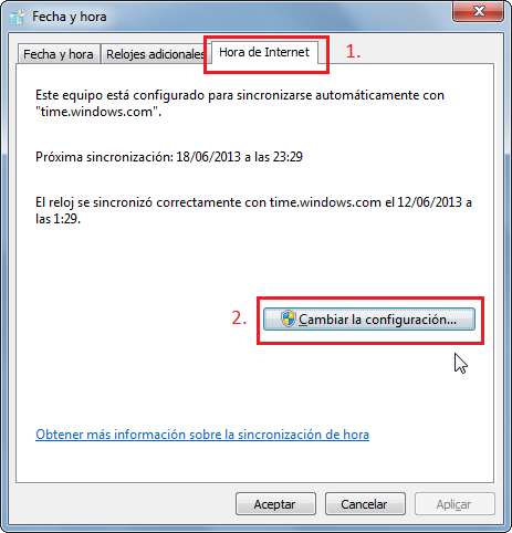
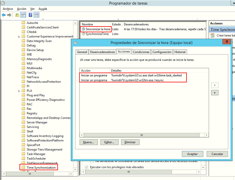
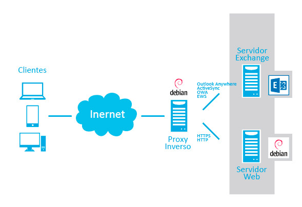
Cuando se complica la infraestructura de servidores puede ocurrir que diferentes servicios necesiten compartir el mismo puerto. Es el caso de Exchange y un servidor web seguro (HTTPS).

Actualmente dispongo de un servidor web, en el puerto 80 de la ip pública y de un servidor de Exchange en el puerto 443. El problema viene cuando en el servidor web queremos servir webs seguras (HTTPS) con certificados SSL. Esto se hace también por el puerto 443, por lo que entra en conflicto con Exchange. Soluciones:

  1. Contratar una segunda IP pública, y ejecutar el servidor web en una IP y el servidor Exchange en la otra
  2. Cambiar el puerto de Exchange al 444, por ejemplo. Microsoft no facilita este cambio, pero si buscas en internet verás que se puede hacer a través del registro de Windows. La desventaja de esta solución es que tendrás que reconfigurar todos los dispositivos (PCs, móviles…) para que ahora apunten al nuevo puerto.
  3. Configuar un proxy inverso que escuche en el puerto 443, que se encargue de atender las solicitudes y derivarlas a quién correspondan, derivarla al servidor web o al servidor de Exchange según corresponda. Esta es la solución que yo he elegido.

Para montar el Proxy reverse he elegido Debian 8 Jessie con Apache haciendo de Reverse Proxy. Configurar el proxy reverse para que por ejemplo atienda diferentes solicitudes HTTP y HTTPS y las derive a diferentes servidores web de la LAN es relativamente sencillo y hay un montón de tutoriales en la red. Configurar un Reverse Proxy para que funcione con Exchange es un infierno. Exchange utiliza RPC sobre HTTP, pero como suele ocurrir con Microsoft, una versión «muy suya», no el estándar. Esa es básicamente la clave para hacerlo funcionar, entender que el RPC de Exchange no es el normal.

Los pasos que yo he seguido son:

1. Crear certificado Let’s Encrypt con certbot en la máquina Apache que ejecuta el Reverse Proxy

2. Exportar el certificado a pfx con openssl para poder usarlo en Exchange:

openssl pkcs12 -export -out certificate.pfx -inkey privkey.pem -in cert.pem -certfile chain.pem

Como veis el mismo certificado tiene que estar instalado en la máquina que hace de Proxy Reverse y en la de Exchange

3. Instalar el certificado pfx en Exchange (yo lo hago a través de IIS)

4. Habilitar los módulos necesarios en Apache para poder hacer Reverse Proxy

a2enmod ssl
a2enmod proxy
a2enmod proxy_balancer
a2enmod proxy_http

Y el super importante para que funcione Exchange:

apt-get install libapache2-mod-proxy-msrpc
a2enmod proxy_msrpc

Ojo porque dependiendo de la distrubición de Linux que uses puede ser que este módulo tengas que configurarlo a mano. En mi caso Debian lo incluye.

5. Crear un Virtual Host en Apache para que haga Reverse Proxy, enlazando el certificado creado y redirigiendo las peticiones a la máquina que ejecute Exchange:

<VirtualHost *:80>
ServerName mail.midominiopublico.es
ServerAlias autodiscover.midominiopublico.es
ServerAdmin tomascrespo@midominiopublico.es

ErrorLog /var/log/apache2/error.log
CustomLog /var/log/apache2/access.log combined

Header always set X-Frame-Options SAMEORIGIN

Header set Server Apache

Header unset X-AspNet-Version
Header unset X-OWA-Version
Header unset X-Powered-By

# Nachfolgende zeile löst den "Expectation Failed Apache 417" Fehler beim AutoDiscover etc.
RequestHeader unset Expect early

# Nachfolgende Zeilen sind um die Authentifizierung zu ermöglichen - NTLM-Funktioniert durch den Proxy nicht, deshalb Basis-Authentifizierung erzwingen
SetEnvIf User-Agent ".*MSIE.*" value BrowserMSIE
Header unset WWW-Authenticate
Header add WWW-Authenticate "Basic realm=midominiopublico.es"

ProxyRequests Off

RewriteEngine On
RewriteCond %{HTTPS} !=on
RewriteRule ^/owa(.*) https://midominiopublico.es/owa$1 [R,L]
RewriteRule ^/ecp(.*) https://midominiopublico.es/ecp$1 [R,L]
RewriteRule ^/Microsoft-Server-ActiveSync(.*) https://midominiopublico.es/Microsoft-Server-ActiveSync$1 [R,L]

DocumentRoot /var/www/midominiopublico.es/web

<Directory />
 Order deny,allow
 Deny from all
</Directory>

<Directory /var/www/midominiopublico.es/web>
 DirectoryIndex index.php index.html
 Options -Indexes +FollowSymLinks
 Order allow,deny
 Allow from all
</Directory>

<Proxy *>
 Order deny,allow
 Allow from all
</Proxy>

</VirtualHost>


<VirtualHost *:443>

ServerName midominiopublico.es
ServerAlias autodiscover.midominiopublico.es


ServerAdmin tomascrespo@midominiopublico.es

ErrorLog /var/log/apache2/error.log
CustomLog /var/log/apache2/access.log combined

Header always set X-Frame-Options SAMEORIGIN

Header set Server Apache

Header unset X-AspNet-Version
Header unset X-OWA-Version
Header unset X-Powered-By

RequestHeader unset Expect early

#SetEnvIf User-Agent ".*MSIE.*" value BrowserMSIE
Header unset WWW-Authenticate
Header add WWW-Authenticate "Basic realm=midominiopublico.es"

ProxyRequests Off
ProxyPreserveHost On


SSLProxyEngine On
# Problemen mit Kommunikation zwischen Apache-Proxy und Exchange-Server aus dem Wege gehen
# Alle SSL Prüfungen werden damit ausgeschaltet
SSLProxyVerify none
SSLProxyCheckPeerCN off
SSLProxyCheckPeerName off
SSLProxyCheckPeerExpire off

# owa
ProxyPass /owa https://maquinaexchange.local/owa
ProxyPassReverse /owa https://maquinaexchange.local/owa
ProxyPass /OWA https://maquinaexchange.local/OWA
ProxyPassReverse /OWA https://maquinaexchange.local/OWA
ProxyPass /Owa https://maquinaexchange.local/Owa
ProxyPassReverse /Owa https://maquinaexchange.local/Owa

# Einstellungen um per OWA das Kennwort zu aendern
ProxyPass /iisadmpwd https://maquinaexchange.local/iisadmpwd
ProxyPassReverse /iisadmpwd https://maquinaexchange.local/iisadmpwd

# ecp
ProxyPass /ecp https://maquinaexchange.local/ecp
ProxyPassReverse /ecp https://maquinaexchange.local/ecp
ProxyPass /ECP https://maquinaexchange.local/ECP
ProxyPassReverse /ECP https://maquinaexchange.local/ECP
ProxyPass /Ecp https://maquinaexchange.local/Ecp
ProxyPassReverse /Ecp https://maquinaexchange.local/Ecp

# ews -> Exchange Web Services
ProxyPass /ews https://maquinaexchange.local/ews
ProxyPassReverse /ews https://maquinaexchange.local/ews
ProxyPass /EWS https://maquinaexchange.local/EWS
ProxyPassReverse /EWS https://maquinaexchange.local/EWS
ProxyPass /Ews https://maquinaexchange.local/Ews
ProxyPassReverse /Ews https://maquinaexchange.local/Ews
ProxyPass /exchange https://maquinaexchange.local/exchange
ProxyPassReverse /exchange https://maquinaexchange.local/exchange
ProxyPass /Exchange https://maquinaexchange.local/Exchange
ProxyPassReverse /Exchange https://maquinaexchange.local/Exchange
ProxyPass /exchweb https://maquinaexchange.local/exchweb
ProxyPassReverse /exchweb https://maquinaexchange.local/exchweb
ProxyPass /public https://maquinaexchange.local/public
ProxyPassReverse /public https://maquinaexchange.local/public

# oab (Offline Address Book)
ProxyPass /oab https://maquinaexchange.local/oab
ProxyPassReverse /oab https://maquinaexchange.local/oab
ProxyPass /OAB https://maquinaexchange.local/OAB
ProxyPassReverse /OAB https://maquinaexchange.local/OAB

# Microsoft-Server-ActiveSync
ProxyPass /Microsoft-Server-ActiveSync https://maquinaexchange.local/Microsoft-Server-ActiveSync connectiontimeout=600
ProxyPassReverse /Microsoft-Server-ActiveSync https://maquinaexchange.local/Microsoft-Server-ActiveSync

<Directory /Microsoft-Server-ActiveSync>
# Problem mit dem Versenden von Dateianhängen > 128KByte per ActiceSync umgehen (neuer Wert 30MByte)
SSLRenegBufferSize 31457280
</Directory>

# RPC over http(s) / Outlook Anywhere
OutlookAnywherePassthrough On
ProxyPass /rpc https://maquinaexchange.local/rpc
ProxyPassReverse /rpc https://maquinaexchange.local/rpc

# AutoDiscover -> Autodiscover for non-AD integrated Clients (Mac, eg.)
ProxyPass /autodiscover https://maquinaexchange.local/autodiscover
ProxyPassReverse /autodiscover https://maquinaexchange.local/autodiscover
ProxyPass /Autodiscover https://maquinaexchange.local/Autodiscover
ProxyPassReverse /Autodiscover https://maquinaexchange.local/Autodiscover
ProxyPass /AutoDiscover https://maquinaexchange.local/AutoDiscover
ProxyPassReverse /AutoDiscover https://maquinaexchange.local/AutoDiscover

# Zeichensatz spezifieren fuer Umlaute
AddDefaultCharset ISO-8859-1

DocumentRoot /var/www/midominiopublico.es/web

<Directory />
 Order deny,allow
 Deny from all
</Directory>

<Directory /var/www>
 DirectoryIndex index.php index.html
 Options -Indexes +FollowSymLinks
 Order allow,deny
 Allow from all
</Directory>

<Proxy *>
 SetEnv proxy-nokeepalive 1
 SetEnv force-proxy-request-1.0 1
 Order deny,allow
 Allow from all
</Proxy>

SSLEngine on

Include /etc/letsencrypt/options-ssl-apache.conf
 SSLCertificateFile /etc/letsencrypt/live/midominiopublico.es/fullchain.pem
 SSLCertificateKeyFile /etc/letsencrypt/live/midominiopublico.es/privkey.pem


 BrowserMatch "MSIE [2-6]" \
 nokeepalive ssl-unclean-shutdown \
 downgrade-1.0 force-response-1.0
 # MSIE 7 and newer should be able to use keepalive
 BrowserMatch "MSIE [17-9]" ssl-unclean-shutdown

# old Server config
 #BrowserMatch ".*MSIE.*" \
 # nokeepalive ssl-unclean-shutdown \
 # downgrade-1.0 force-response-1.0
</VirtualHost>

Como veis también hay un VirtualHost para el puerto 80, que lo único que hace es redirigir las peticiones HTTP para que se conviertan en HTTPS, al puerto 443 que es por donde deben de ir.

6. Probar y añadir sal al gusto.


Notas:

Los PC con Outlook fuera de la LAN usan Outlook Anywhere para conectarse, o lo que es lo mismo RPC sobre HTTP

Los Mac con Outlook fuera de la LAN usan Exchange Web Services (EWS) para conectarse.

Tanto Outlook AnyWhere como Exchange Web Services (EWS) y Offline Address Book (OAB) tienen que tener habilitada la Autenticación Básica, pues Apache Reverse Proxy no es capaz de manejar la Autenticación NTLM.

La Autenticación Básica de EWS y OAB se habilita en IIS, en el directorio virtual /EWS, en el apartado Autenticación

A mi actualmente me está funcionando todo desde fuera de la oficina:

  • Outlook Web Access (OWA)
  • iPhones, móviles Android y móviles Windows Phone con ActiveSync
  • Portátiles de los jefes MacBook Air que usan EWS (con Outlook for Mac)
  • Portátiles Windows  con Outlook, que usan Outlook Anywhere

Referencias: Apache2 als Reverse Proxy für Exchange 2010 2013 inklusive Outlook Anywhere RPC over http

Convert letsencrypt .pem certificate to .pfx

I use Let’s Encrypt certificates in my Windows and Linux serves. This week I had to use the same certificate in two machines, one IIS server (Windows) and one Apache2 server (Linux Debian).

I create the certificate in Linux using certbot utility, ant it gave me four files:

  • cert.pem
  • chain.pem
  • fullchain.pem
  • privkey.pem

I installed to Apache with no problems.

But then I tried to install the certificate to IIS 6.1 and I realized that Windows did not want that type of file. With some research on the Internet I found a solution, using the command openssl (in Linux):

openssl pkcs12 -export -out certificateforwindows.pfx -inkey privkey.pem -in cert.pem -certfile fullchain.pem

I wish this helps someone

Yi Home Camera 2 1080p + Xiaomi Power Bank 2c 20.000mAh

Description

Sometimes I need a camera in some places where there is no easy power supply, so I have to run with a battery. I usually use a UPS, like the one we use for ower computers, but this machine converts from a 12v battery to 220v output, and then, the Yi Home Camera transformer convert from 220v to 5v.

So I thought using a power bank (those which we use to recharge our mobile in a emergency) to avoid even the  transformer. I bought the bigger I found, Xiaomi Power Bank 2C 20.000mAh.


Theoretical calculations

The power supply of the Yi Camera is 5v 2.0A. In the Yi Home Camera 2 is noted 4.0W(MAX).
If the camera consumes 4 watts for 24h it involve 96Wh
The battery is rated at 20.000 mAh and 5v, that is 100Wh.

With these data, and assuming that the camera is always at max consumption, (4W) it should last: 100/96 = 25h, a bit more than a day. That assuming:


  1. The battery could be fully discharged. False, Li-polymer battery can be discharged 80% as much
  2. The camera consumes 4W all the time. False, I have tested the camera with a consumption-meter for a full week and it consumes 2.4W in average.

So now the calculations are:  (80%100Wh)/(2.5w24h) = 80/60 = 32h

Let’s check.

In Practice

Now my test. I full charged the power bank, set it to low current output mode (according to power bank user guide this funcion is for small devices, fitness bands, watches, bluetooth headsets and other small gadgets), and place the camera in my cottage. I set it up recording continiously (not only when motion is detected) at 1080p @25fps (max quality) and disabled all other stuff like gesture recognition o baby crying recognition. The camera was with no WiFi connection (perhaps it was searching for WiFi all the time and that is a battery consuming operation). It started recording August 19, 2018 at 20:56h, and the last slice of recording was at August 21, 2018 at 06:37h.

So, my Yi Home Camera 2 connected to a Xiaomi Power Bank 2C as power supply continuosly recording last 33 hours and 41 minutes.

Wow!!! Only a 4,3% of  deviation between theory and reality.

Next tests:

  • With WiFi connection linked, not always searching.
  • With motion detection only recording. I suposse it will increase autonomy because of not writing continiously to the sd card. On the other hand motion detector is a CPU consuming operation…

Anyway if you got here, perhaps you have to have a look to Blink cameras and this Blink cameras with AA batteries but be aware of region lock before purchasing one.

How to use Yi Home Camera 2 (1080p) outside of China, revisited

Firstly, this post is about Yi Home Camera 2. Currently Xiaoyi has various similar models. In each one of its models they make a Chinese version and an international version (same version but more expensive). Xiaoyi is making big efforts to block using Chinese models outside of China, forcing you to buy a international version.

I wrote an article some time ago to get this camera working, but after that Xiaomi enhanced its blocking procedure and this article is not valid any more.

Now Xiaomi has introduced a new change, checking if your camera is connecting to their servers from a Chinese IP address or not.

Description of the problem

Yi Home Camera 2 is paired with Yi app with no problem, the camera works and save video on the SD card, even notify you when there is some event, but you can NOT get live video. When you open Yi app it stucks at Establishing secure channel… 50% for a while and finally it shows the error message Network connection failed, please check network settings and reconnect it (-20009). So neither you  can watch your camera on live or browse through your records from the Yi app. However you can get out the SD card and review your videos in a PC.

The solution

In brief the solution is using a Chinese proxy, so Xiaomi will think your camera is in China. Easy, isn’t it?

Fortunately there is a project (yi-hack-v2) where someone (niclet) has made a custom firmware to get telnet and FTP working for this camera and, the most important for us, with an option to setup a proxy. So all the credits go for him/her.

The procedure to get your camera working again is:

  1. Download the files of niclet project and copy the contents of sd folder to the root of your SD card. The card has to be FAT32 (vfat) formated.
  2. Edit the file yi-hack-v2.cfg (in test folder) and uncomment the last line (remove the starting ‘#’), and set one Chinese server (I use this list)
  3. Put your SD card. All is done. Now you can pair it with your Yi Chinise phone app an get Live video with no problems

Note 1: The text editor to edit file yi-hack-v2.cfg is important. Its a linux file, someway different to a Windows one. I firstly used notepad and the hack doesn’t work. I then used Notepad++ and it worked perfectly. Mind this if you are having any trouble.

Note 2: If you have some trouble formatting you SD card with Windows, you could use HP USB Disk Storage Format Tool

Note 3: You have to download the files of niclet project (yi-hack-2) from github, but if you have any problems they are here too.

Note 4: I’ve got better results pairing the camera without the SD card, and then inserting it (after pairing success).

Currently my last line of yi-hack-v2.cfg is:

YI_HACK_PROXY=socks4://123.59.100.246:1080

and with this proxy the camera is working for three months.

YI_HACK_PROXY=socks5://103.85.24.43:7982


Dominios Windows .local y problemas con Apple

Desde hace algún tiempo estoy problema con los dominios Windows de algunas empresas, dominios Active Directory, y los productos de Apple, especialmente con iPhone y iPad (aunque po lo que veo hay gente que también tiene problema con los Mac).

El problema surgió porque los productos de Apple no recibian email (mediante ActiveSync del servidor Exchange que tenemos en la empresa) cuando estaban conectados al WiFi de la empresa, pero sin embargo sí que recibian email cuando estaban fuera de la empresa.

El problema es que cuando están dentro de la empresa son incapaces de resolver el nombre del dominio, pues es un dominio interno del tipo midominio.local, mientras que cuando están fuera de la empresa utilizan midominio.com. Tras mucho estrujarme la cabeza doy con la información de que ahora (a saber desde cuándo, pues antes funcionaban perfectamente) Apple utiliza el sufijo .local para Bonjour (lo trata como host Rendezvous), por lo que al ver que es un dominio .local no resuelve mediante DNS, sino que resuelve mediante Bonjour, o lo que es lo mismo, no resuelve.

Hay muy poca información al respecto en internet sobre este tema, así que aquí dejo un par de links.

El artículo técnico de Apple. Ofrece solución para los Mac, pero no para los iPhone/iPad.
Uno de los problemas en los foros de Microsoft.
Otro problema en spiceworks.

¿Y que hay de las soluciones? ¿cambiar el sufijo de tu dominio Windows por algo del tipo midominio.loc? Venga, es muy divertido cambiar el nombre de un dominio!

Aquí las mejores prácticas que recomienda Microsoft para elegir un nombre de dominio Windows.

Probablemente por esto Microsoft ha dejado de recomendar utilizar .local para sus dominios Active Directory y ahora recomienda usar un subdominio del dominio público.

How to use Yi Home Camera 2 (1080p) outside of China

UPDATE (11/11/2017): This process is not valid anymore, but you can use a new one. All info here.

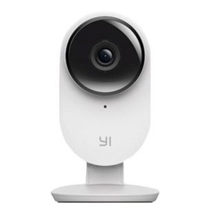
I’ve been using a Yi Homme Camera for a long (aka Xiaomi/Xiaoyi Small Ants Camera). It’s a magnific camera with good quality (720p) and night vision at a stunning price. In my opinion, then only flaw is the lack of an wired Ethernet port. However, Xiaomi, firmware update after firmware update has made it a bit worse. First they blocked telnet access, RTSP and HTTP. And finally the blocked their Chinese hardware to be used only in China Mainland (from Nov 2015). Yes, they sell two versions, Chinese and International. Luckily you always can solve this limitations running some scripts or downgrading the firmware. There is a lot of info on the Internet.


Recently Xiaomi (Yi) launched a major upgrade for this product. They presented Yi Home Camera 2, with even better quality, 1080p @25fps 1.5Mbits, gesture detection and more. Obviusly I immediately bought one. However I got the same issue all people is having. It’s impossible to get it working. You can not pair it with the phone app. The camera gets the QR code, connect to your WIFI network (light steady blue light) but the pairing proccess never ends succesfully. You get “time out” both the camera (voice message) and the phone. Every people has the same problem. Some of them have tried to update the firmware, but this is even worse. Now they get a voice message “This camera can only be used in China”.

After some weeks of research I finally get mine working, using a specific firmware.

To install it you have to:

    1. Download this firmware (version 2.1.1-20160429113900) and put it in the root of your SDCARD (it has to be FAT32 formated). The name of the file has to be home.bin, otherwise camera won’t install it
    2. Turn on the camera
    3. Reset the camera to default values pressing the reset white button in the back
    4. Turn the camera off
    5. Insert the SD card with home.bin and turn it on

You will see the green led blinking for about one minute. After that you will be able to pair your camera with the app. Bear in mind that the app has to be Chinese version too.

And, of course, remember NOT to update your camera firmware even if the phone app invite you.

Next step: Enable telnet to allow RTSP and FTP.

Date and Time in Xiaomi Xiaoyi Smart Camera

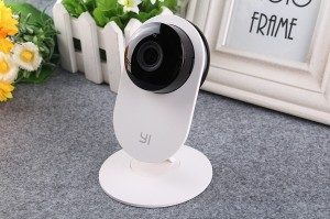
Sometimes you find out a small gem like this beautifull piece of hardware. Xiaoyi Smart Camera is almost the perfect home camera. It has a beutiful design, good video quality, bidirectional sound, good construction, SD card slot, WIFI, a decent mobile app, and a bargain price. However it has some drawbacks:

  • Latest firmwares have removed telet, FTP and RTSP access. WHY?
  • Time Zone is stuck to China, so your recordings are miss-dated, what does moving through recordings by the mobile application a nightmare.
  • Lack of wired networking.

I can accept the lack of wired networking but not the other two. The first was present in early firmwares. The Time Zone setting would be really easy to add. There are some alternatives on the Internet to fix the Time Zone issue but while helping they don`t solve the problem.

Solution 1

Disable ntpdate (from here):

I telnetted into the camera (username: root / password: 1234qwer)

Code:
cd /homemv ntpdate ntpdate.orig
touch ntpdate
chmod 755 ntpdate
date -s “2015-06-02 22:00″

The commands above disable to program that tries to set the date from the internet, and then you can set the date manually to the current date/time. Hope this helps.

Of course, to be able to apply this solution you have to flash one firmware with telnet support.
Drawbacks:

Solution 2

Firmware mod (from here)


If you are living in a different time zone (GMT+6 is Germany, Denmake, Austria, Italy…) you have to download the file “equip_test.sh” open and modify the row. The line “my_version =” should contain possible the latest version of the firmware.

Drawbacks:

  • While the timestamp on the video is fixed, the orange marks in mobile app timeline not, so moving through it doesn’t work very well.

Solution 3

Changing time zone in etc (from here)

Hello,
You can change the timezone.
Change the TZ file in /etc/
the command is :
echo “$my_gmt” > /etc/TZ
change $my_gmt by your timezone.
Note : GMT 0 => Beijing
for Paris = GMT+6
Have fun.


My solution

Work in progrress: I’ve create a bash scritp which changes the time of the mp4 files created by the camera to a previous date, 6 hours before. The script is executed every minute through cron.


Update: The best solution

Finally, the best solution it’s here and it does suppot moving through recordings perfectly.

Sincronización del reloj con la hora de Internet

Uno de los servidores de una empresa está teniendo problemas
con el reloj de Windows (Windows Server 2012). El reloj se atrasa de
forma aleatoria, llegando a marcar incluso un día menos de la fecha
actual. Siendo el servidor un controlador de dominio (relaciones de
confianza y sincronización de la hora con los equipos del dominio),
centralita teléfonica (no se puede llamar a determinadas horas) y
gestionar la facturación (fechas de facturas erróneas) esto se convierte
en un gran problema. Lo primero por supuesto fue pensar que la pila del CMOS se había gastado, y simplemente con sustituir la sería suficiente, pero no es así, pues la hora se retrasa sin ni siquiera tener que apagar o
reiniciar el equipo, sino mientras Windows está en funcionamiento,
cuando la pila no entra en juego.

Teniendo en cuenta que la placa basae de ese mismo servidor ya ha
dado algún problema de hardware, cabe suponer que debe ser algo de lo
mismo. Así, y en vista de que el cliente no quiere sustituir el
servidor, la solución a adoptar es conseguir que el relog se sincronice
con la hora de internet para evitar ese retraso. Como sabemos Windows ya
ofrece esa posibilidad, como una opción más del reloj, pero la
sincroniza cuando el quiere, lo que provoca que el reloj siga
atrasándose.

configurar-fecha-y-hora


Así pues había que buscar otra solución.

La orden de línea de comandos W32tm.exe /resync fuerza la
sincronización del reloj con la hora de internet (time.windows.com, o el
servidor NTP que esté configurado), dejando la fecha y la hora
perfectas.

Así, la solución fue crear una tarea programada que ejecutase esta
orden cada 15 minutos, para asegurarnos de que el reloj estuviese
siempre sincronizado. La tarea viene a ser esta:

tarea-sinc

Quizás la primera línea podría omitirse, pero está para asegurarnos
de que el servicio de sincronización de la hora está ejecutándose, no
vaya a ser que esté dormido.